Diese Seite auf Deutsch: Balkenrechner
![]()
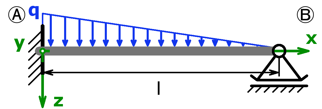
This online beam calculator calculates the forces and moments in the two bearings (= support reactions) and the angles of inclination of statically determined or statically indeterminate beams. In addition, the lateral force, the bending moment, the bending stress and the deflection can be determined at a desired location. The bending moment, the shear force and the deflection as a function of the length x are shown graphically in two diagrams. The calculation of the maximum bending moment, the maximum bending stress, the maximum deflection and the associated position is possible, too.
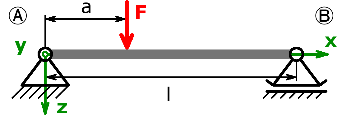
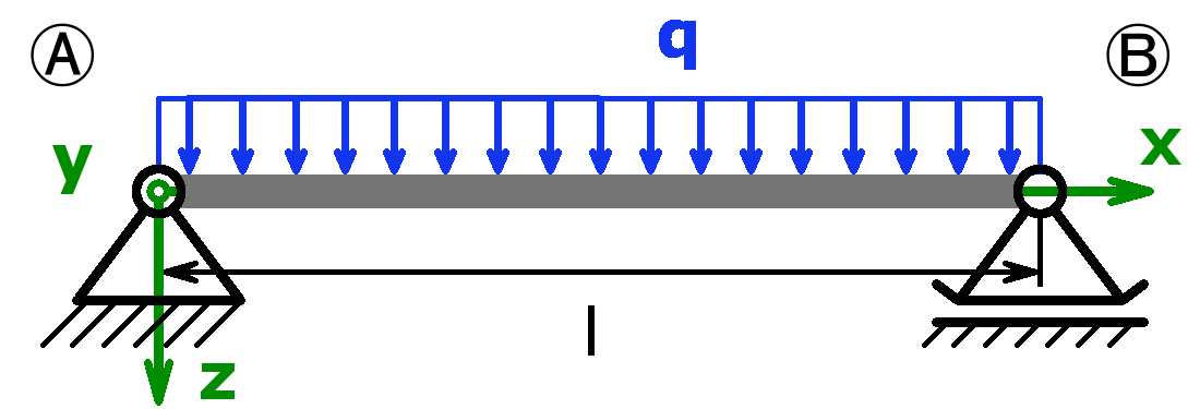
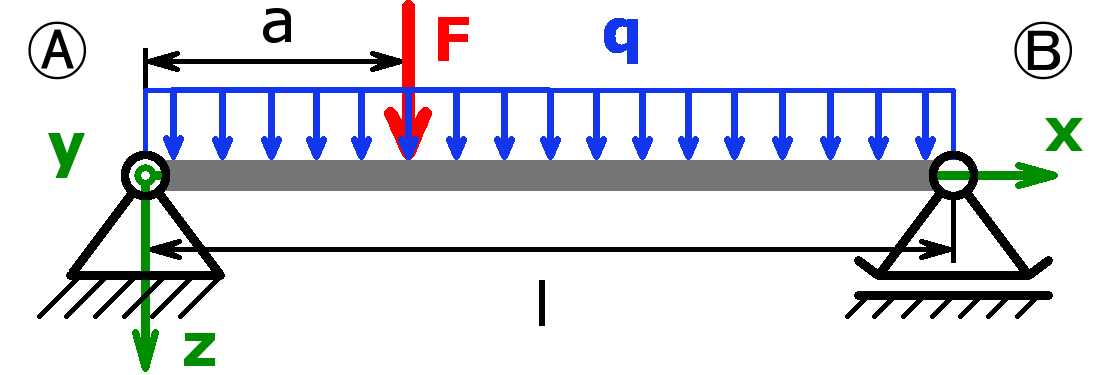
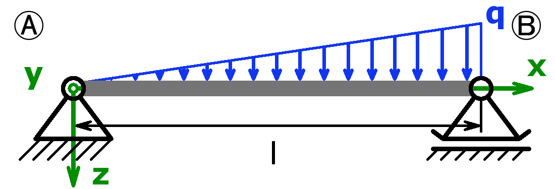
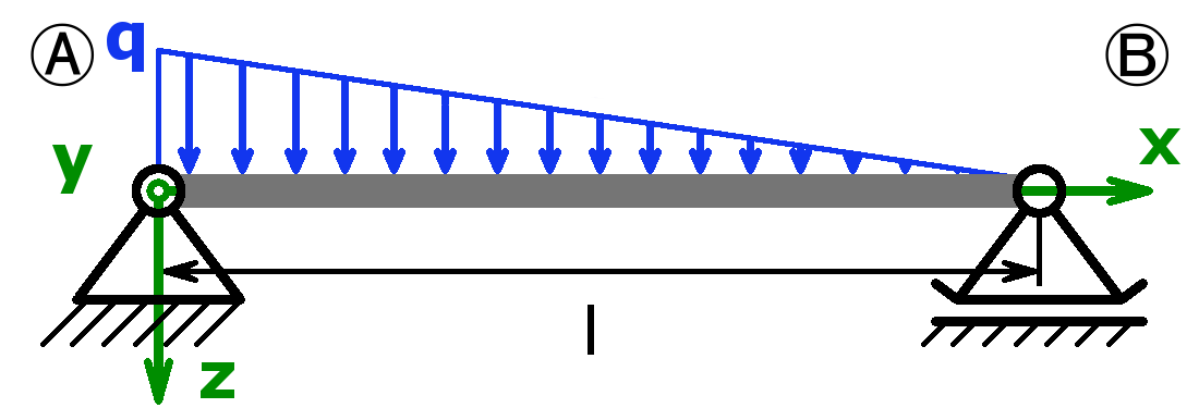
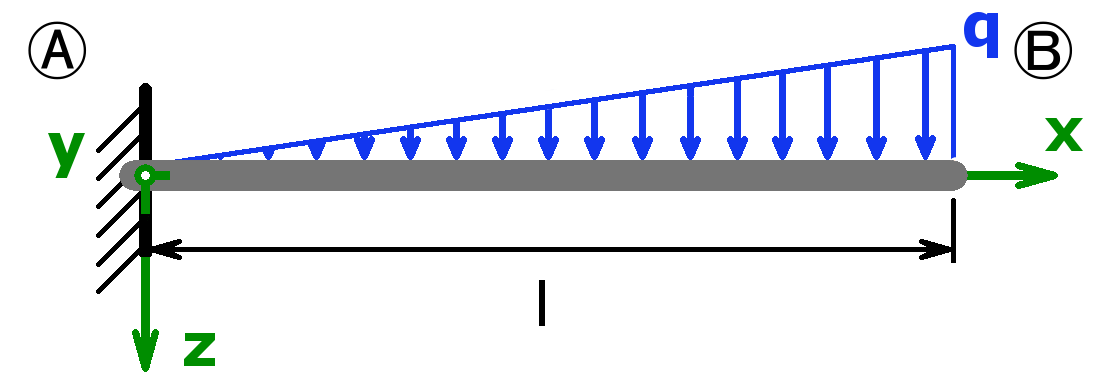
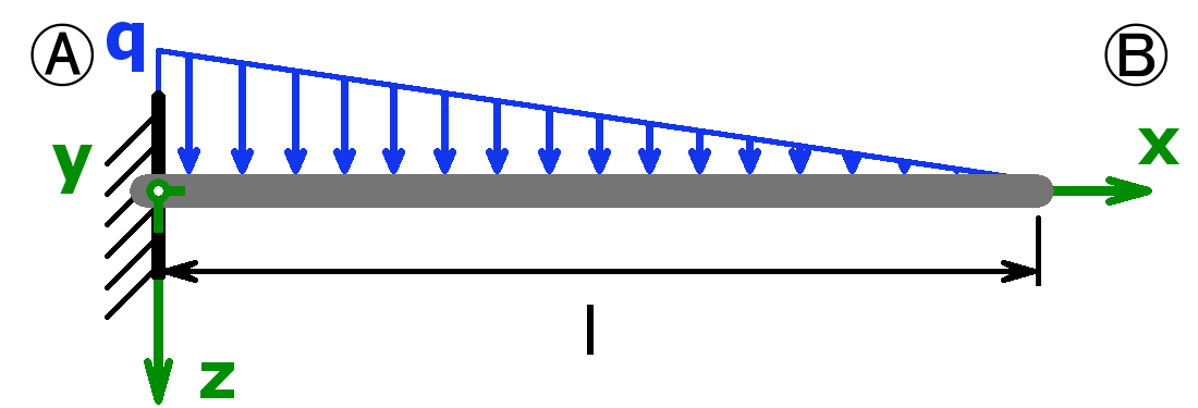
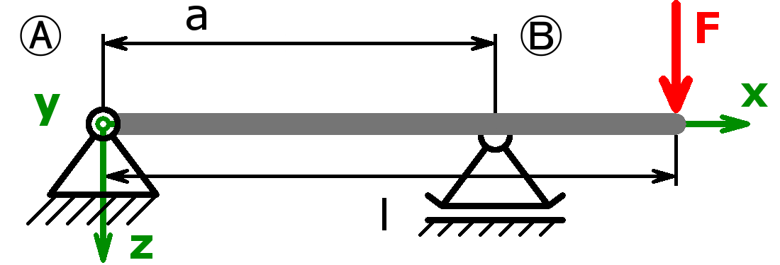
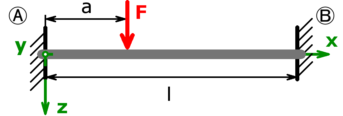
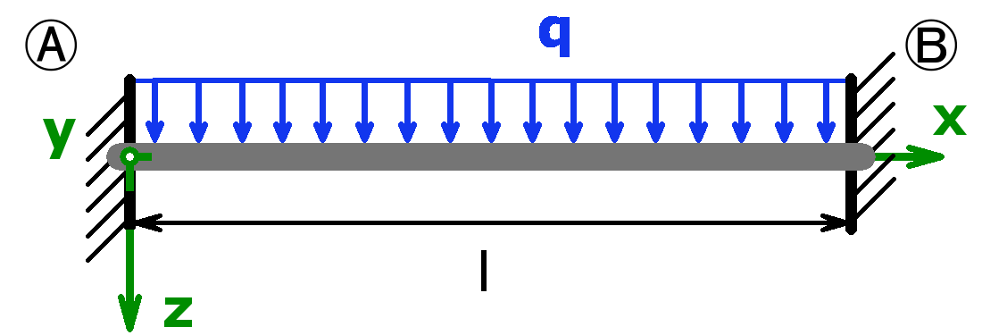
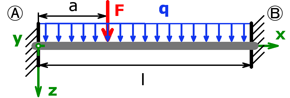
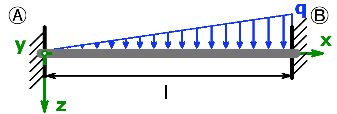
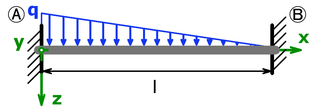
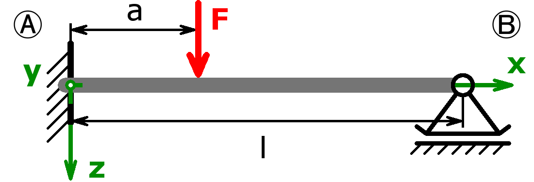
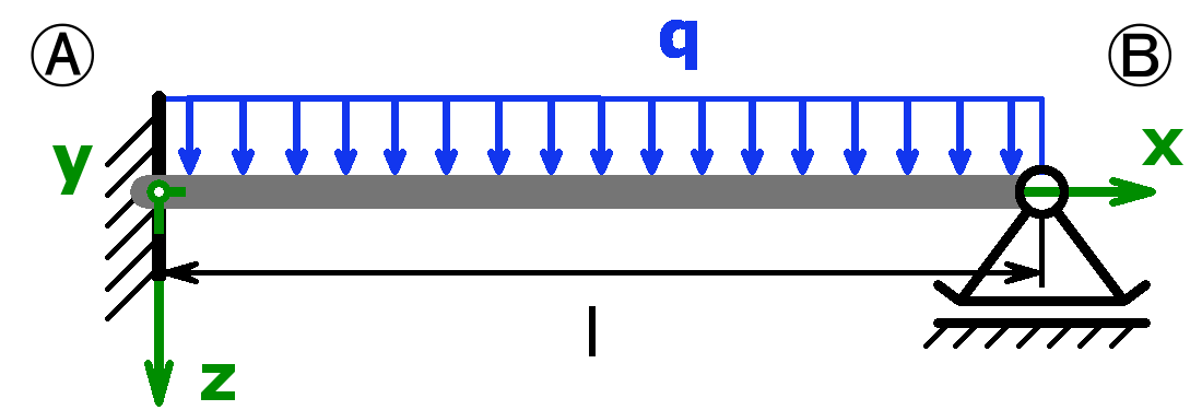
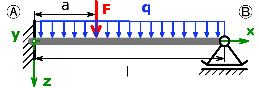
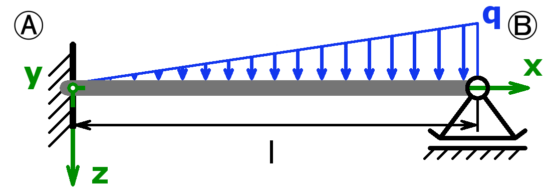
The bearings can be designed as a fixed bearing, a movable bearing, a fixed clamping or as a free end. As a load, a equal load or a point load or the combination of both or a triangular load (left or right) can be selected.
In the moment this calculator isn’t working. Please use the german version instead:
Calculator for Support Reactions, Lateral Force & Bending Moment of Beams
* To enter these values, select under Cross section A -> Other profiles -> „Own profile“.
** The modulus of elasticity is automatically entered by selecting a material and can be changed at any time; suitable valuesyou can find on wikipedia for example.
Caution:
For profiles with a hole, only I, W and the maximum bending stress are calculated correctly under the additional functions. For the other values, choose a profile without hole!
Explanation of the abbreviations
| FA | reaction force in bearing A in z-direction; in the x-direction there are no forces! |
| FB | reaction force in bearing B in z-direction; in the x-direction there are no forces! |
| MA | clamping moment in bearing A |
| MB | clamping moment in bearing B |
| xM.m |
position of the maximum bending moment; Attention: only one place is calculated even if there are several equal bending moments! |
| My.m | maximum bending moment |
| x |
point where the bending moment, the lateral force, the bending stress and the maximum deflection are to be calculated |
| My (x) | bending moment at the point x |
| Q (x) | lateral force at the point x |
| A | cross section of the profile |
| mat. | material |
| E |
Young’s modulus / modulus of elasticity, suitable values you can find on wikipedia for example |
| Iy | area moment of inertia |
| Wy | section modulus |
| σx | bending stress in the outer-fibre at the point x |
| σx.m | maximum bending stress in the beam at the point xM.m |
| αA | inclination angle of the beam in bearing A |
| αB | inclination angle of the beam in bearing B |
| xf.m | position of the maximum deflection of the beam |
| fm | maximum deflection of the beam at the point xf.m |
| f (x) | deflection of the beam at the point x |
Manual
- The following cross sectional areas are available, whereby profiles marked by * can have a clearance hole (bore), too:
- circle *
- pipe / hollow circular
- semi-circle
- rectangle-section *
- rectangle-pipe / hollow rectangular *
- I/H-section (I/H-beam) *
- U/C-section (U/C-beam) *
- T-section (T-beam)
- L-section (angle section), isosceles and not isosceles
- L-section (isosceles) rotated through 45°
- isosceles triangle
- hexagon / six-sided figure
- octagon / eight-sided figure
- The loads may also be negative.
- Any jumps in the lateral force curve can not be displayed correctly.
- Accuracy can not be guaranteed – for corrections or additions please use mycontact form!
Selectable combinations
The support forces of both statically determined and statically indeterminate systems can be calculated by this calculator. The following combinations are possible:
Statically determined systems
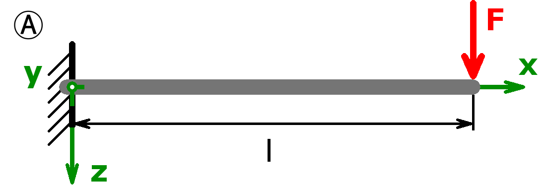
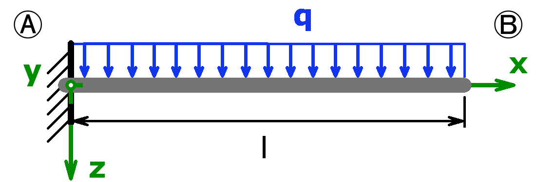
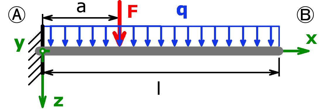
Statically indeterminate systems
Seite erstellt im November 2017. Last change: