Diese Seite auf Deutsch: Flächenrägheits- und Widerstandsmoment-Rechner
![]()
This online calculator computes the axial and polar area moments of inertia (also known as second moment of area or second area moment), the section modulus, the outer-fibre distance and the cross sectional area of many beams. From many surfaces, the torsional moment of inertia and the torsionial section modulus can also be calculated.
In addition, the mass can be computed, too. Steel, aluminum and different types of wood are available as material. At the bottom of the page, the formulas for the axial area moment of inertia and section modulus are listed in a table.
Calculator for Area Moment of Inertia and Section Modulus
By default, one can calculate the moments, mass and cross section for an I-beam (I100).
* You have to fill in these fields only if the mass should be calculated, too. Only the smallest section modulus will be calculated!
Explanation of the abbreviations
| Dm | diameter in mm |
| Iy, Iz | axial area moments of inertia |
| Wy, Wz | section modulus |
| It | torsional moment of inertia |
| Wt | torsional section modulus |
| Ip | polar area moments of inertia: Ip = Iy + Iz for circular cross sections: It = Ip |
| e1-4 | outer-fibre distance, see following section |
Outer-fibre distance
The outer-fibre distance is the distance from the neutral fiber to the outer fibre. For homogeneous cross-sections, the neutral fibre always runs through the center of gravity SP of the surface which lies in the center of the coordinate system. The 4 outer fibres are the furthest away from the respective coordinate axes.
The sketch shows which lengths denote the four outer-fiber distances e1, e2, e3 and e4.
Therefore the lengths e1 and e2 are the vertical outer-fibre distances and the lengths e3 and e4 are to the horizontal outer-fibre distances.
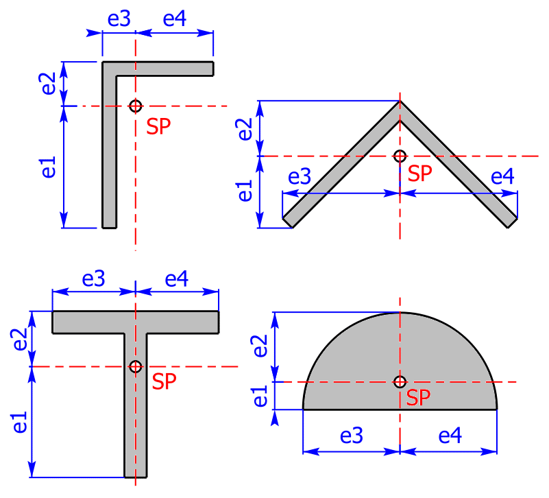
Table of contents
- Some Notes for the Use of the calculator (manual)
- Background Knowledge and Formulas
- Additional Information about the Calculator
Manual
- The following cross sectional areas are available, whereby profiles marked by * can have a clearance hole (bore), too:
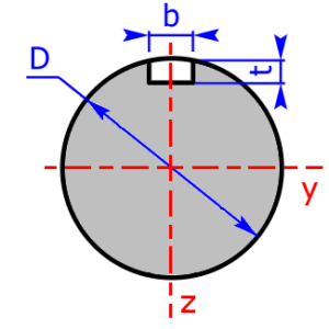
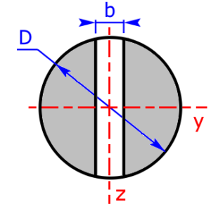
- circle, with slot too *
- pipe / hollow circular
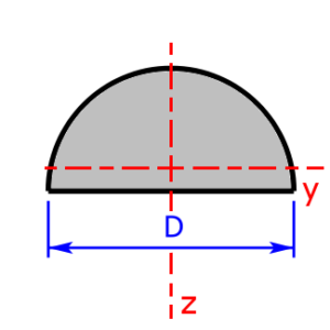
- semi-circle
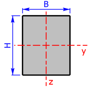
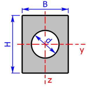
- rectangle-section *
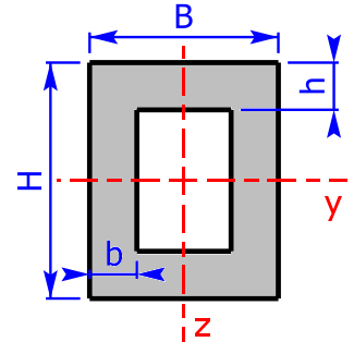
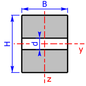
- rectangle-pipe / hollow rectangular *
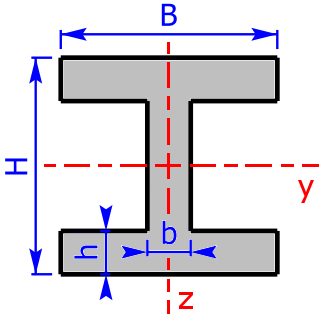
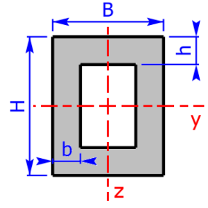
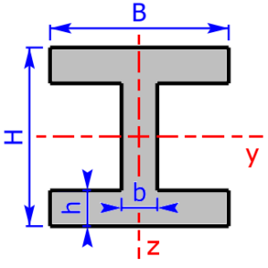
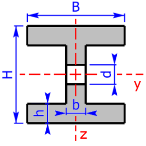
- I/H-section (I/H-beam) *
- U/C-section (U/C-beam) *
- T-section (T-beam)
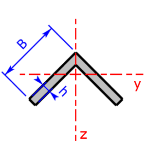
- L-section (angle section), isosceles and not isosceles
- L-section (isosceles) rotated through 45°
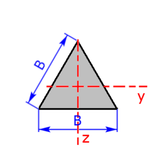
- isosceles triangle
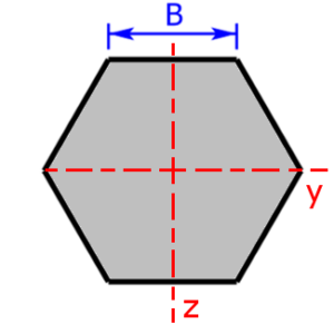
- hexagon / six-sided figure
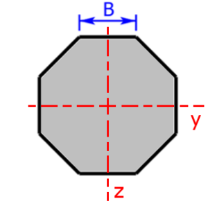
- octagon / eight-sided figure
- Below you will find sketches of all cross sectional areas. The cross sectional areas must always be symmetrical to the two coordinate axes.
- All white fields have to be completed. Results are displayed on a green background.
- Accuracy can not be guaranteed – for corrections or additions please use my contact form!
Background Knowledge and Formulas
In the following table you will find the formulas for the axial area moments of inertia and the section modulus. Then the mathematical relationship between these two quantities is explained.
Formulas for axial Area Moments of Inertia & Section Modulus
The following relationships apply to all the formulas listed in the table below:
- b3 = B – b
- b4 = B – 2·b
- h3 = H – h
- h4 = H – 2·h
| Cross Section | Axial Area Moment of Inertia | Section Modulus |
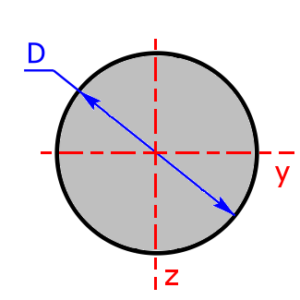
 circle-section
 |
$$I_y=I_z=\frac{\pi·D^4}{64}$$ | $$W_y=W_z=\frac{\pi·D^3}{32}$$ |
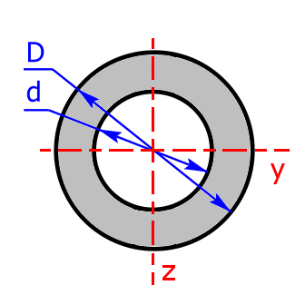 pipe-section
 |
$$I_y=I_z=\frac{\pi·(D^4-d^4)}{64}$$ | $$W_y=W_z=\frac{\pi·(D^4-d^4)}{32·D}$$ |
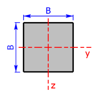
 square-section square-section |
$$I_y=I_z=\frac{B^4}{12}$$ | $$W_y=W_z=\frac{B^3}{6}$$ |
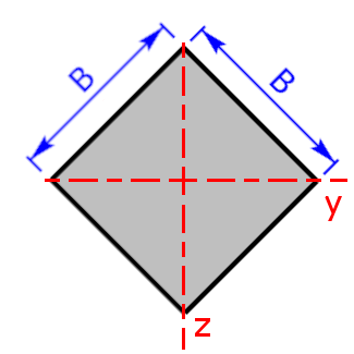 square rotated |
$$I_y=I_z=\frac{B^4}{12}$$ | $$W_y=W_z=\frac{B^3}{6·\sqrt{2}}$$ $$e_{1,2,3,4}=\frac{\sqrt{2}}{2}·B$$ |
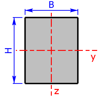 rectangle-section rectangle-section |
$$I_y=\frac{B·H^3}{12}$$ | $$W_y=\frac{B·H^2}{6}$$ |
| $$I_z=\frac{H·B^3}{12}$$ | $$W_y=\frac{H·B^2}{6}$$ | |
 rectangle-pipe rectangle-pipe |
$$I_y=\frac{B·H^3-b_4·(h_4)^3}{12}$$ | $$W_y=\frac{B·H^3-b_4·(h_4)^3}{6·H}$$ |
| $$b_4=B-2·b\qquad h_4=H-2·h\qquad$$ (b4 and h4 = inside dimensions) | ||
| $$I_z=\frac{H·B^3-h_4·(b_4)^3}{12}$$ | $$W_z=\frac{H·B^3-h_4·(b_4)^3}{6·B}$$ | |
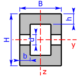
 I/H-section I/H-section |
$$I_y=\frac{B·H^3-b_3·(h_4)^3}{12}$$ | $$W_y=\frac{B·H^3-b_3·(h_4)^3}{6·H}$$ |
| $$b_3=B-b\qquad h_4=H-2·h$$ | ||
| $$I_z=\frac{2·h·B^3+h_4·b^3}{12}$$ | $$W_z=\frac{2·h·B^3+h_4·b^3}{6·B}$$ | |
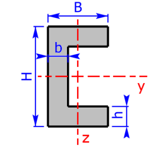
 C/U-section $$b_3= B – b$$ $$h_4=H-2·h$$ |
$$I_y=\frac{B·H^3-b_3·(h_4)^3}{12}$$ | $$W_y=\frac{B·H^3-b_3·(h_4)^3}{6·H}$$ |
| $$I_z=\frac{2·h·B^3+h_4·b^3}{3}-(2·h·B+h_4·b)e_3^2$$ | $$W_{{z}_{1,2}}=\frac{I_z}{e_{3,4}}$$ | |
| $$e_3=\frac{1}{2}·\frac{2·h·B^2+h_4·b^2}{2·h·B+h_4·b}$$ | $$e_4=B-e_3$$ | |
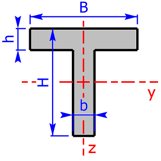 T-section $$b_3=B-b$$ $$h_3=H-h$$ |
$$I_y=\frac{b·H^3+b_3·h^3}{3}-(b·H+b_3·h)·e_2^2$$ | $$W_{y_{1,2}}=\frac{I_y}{e_{1,2}}$$ |
| $$e_2=\frac{1}{2}·\frac{b·H^2+b_3·h^2}{b·H+b_3·h}$$ | $$e_1=H-e_2$$ | |
| $$I_z=\frac{h·B^3+h_3·b^3}{12}$$ | $$W_z=\frac{h·B^3+h_3·b^3}{6·B}$$ | |
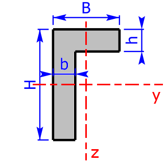 L-section $$b_3=B-b$$ $$h_3=H-h$$ |
$$I_y=\frac{b·H^3+b_3·h^3}{3}-(b·H+b_3·h)·e_2^2$$ | $$W_{y_{1,2}}=\frac{I_y}{e_{1,2}}$$ |
| $$e_2=\frac{1}{2}·\frac{b·H^2+b_3·h^2}{b·H+b_3·h}$$ | $$e_1=H-e_2$$ | |
| $$I_z=\frac{h·B^3+h_3·b^3}{3}-(h·B+h_3·b)·e_3^2$$ | $$W_{z_{1,2}}=\frac{I_z}{e_{3,4}}$$ | |
| $$e_3=\frac{1}{2}·\frac{h·B^2+h_3·b^2}{h·B+h_3·b}$$ | $$e_4=B-e_3$$ | |
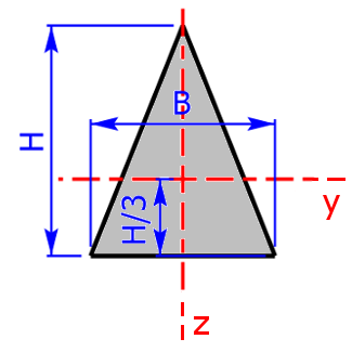 isosceles triangle isosceles triangle |
$$I_y=\frac{B·H^3}{36}$$ | $$W_{y_1}=\frac{B·H^2}{12}\quad e_1=\frac{H}{3}$$ |
| $$W_{y_2}=\frac{B·H^2}{24}\quad e_2=\frac{2·H}{3}$$ | ||
| $$I_z=\frac{H·B^3}{48}$$ | $$W_{z_{1,2}}=\frac{H·B^2}{24}$$ | |
 semi-circle semi-circle |
$$I_y=0.10976·\left(\frac{D}{2}\right)^4=0.10976·r^4$$ | $$W_{y_1}=0.25861·\left(\frac{D}{2}\right)^3$$ |
| $$W_{y_2}=0.19069·\left(\frac{D}{2}\right)^3$$ | ||
| $$I_z=\frac{1}{2}·\frac{\pi·D^4}{64}=\frac{\pi·D^4}{128}=\frac{\pi·R^4}{8}$$ | $$W_{y_{1,2}}=\frac{1}{2}·\frac{\pi·D^3}{32}=\frac{\pi·D^3}{64}$$ | |
 hexagon hexagon |
$$I_y=I_z=\frac{5·\sqrt{3}}{16}·B^4$$ | $$W_y=\frac{5}{8}·B^3$$ |
| $$W_z=\frac{5·\sqrt{3}}{16}·B^3$$ | ||
 octagon octagon |
$$I_y=I_z=\frac{1+2·\sqrt{2}}{6}·B^4$$ | $$W_y=W_z=0.6906·B^3$$ |
Correlation Section Modulus < > Area Moment of Inertia
The section modulus can be calculated by the following formulas if the area moment of inertia and the outer-fibre distance are known.
The section modulus Wy relative to the y-axis is:
$$W_{y_{1,2}}=\frac{I_y}{e_{1,2}}$$
The section modulus Wz relative to the z-axis is:
$$W_{z_{1,2}}=\frac{I_z}{e_{3,4}}$$
| Iy | area moment of inertia relative to the y-axis |
| Iz | area moment of inertia relative to the z-axis |
| e1 | lower outer-fibre distance in the z-direction |
| e2 | upper outer-fibre distance in the z-direction |
| e3 | left outer-fibre distance in the y-direction |
| e4 | right outer-fibre distance in the y-direction |
If the cross sectional area is not symmetrical to an axis (e1 ≠ e2 and/or e3 ≠ e4), there are two different section modulus relative to this axis, see figure above. Only the smallest section modulus will be calculated!
Additional Information about the Calculator
Comparison: idealized model and real I-beam I100
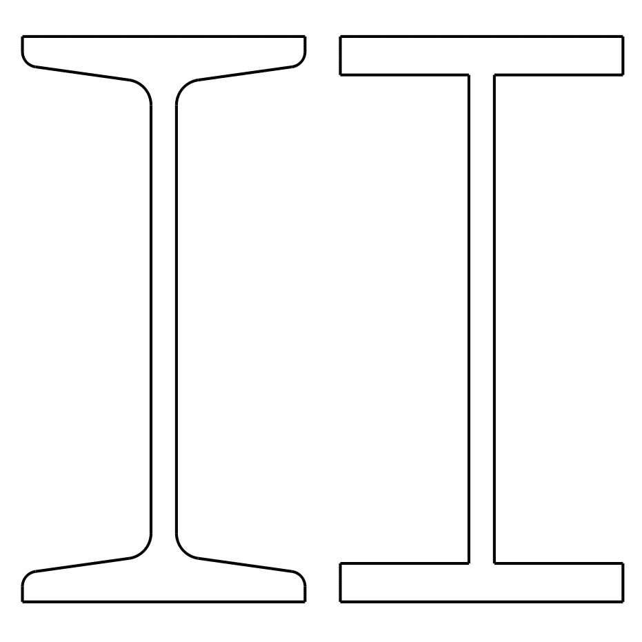
In figure 1 you can see a narrow I-beam I100 on the left, on the right you find a simplified model, as it used by the calculator.
The variations in the calculation arise from the fact that the real I-beam has oblique flange surfaces and the inner edges are rounded. This can be seen very well in figure 1.
All drawings were created by using the free programs FreeCAD and GIMP.
The following table compares the calculated values and the real values:
| Iy in cm4 |
Wy in cm3 |
Iz in cm4 |
Wz in cm3 |
A in mm2 |
m‘ in kg/m |
|
| calculated values | 172.1 | 34.4 | 14.2 | 5.7 | 1069 | 8.40 |
| real values | 171 | 34.2 | 12.2 | 4.88 | 1060 | 8.34 |
| variations in % | 0.64 | 0.58 | 16.4 | 16.8 | 0.85 | 0.72 |
As you can see, Iy and Wy, the cross sectional area A and the mass per meter match very well. The z-values differ slightly more, but are still useful as an estimate.
Sketches of the available cross sectional areas
These 20 profiles can be selected as a cross sectional area on the calculator:


Page created on 04 June 2019. Last change: 25 June 2022.